


SF6-free RMUs | BGS-40.5 part 2
General introduction
- BGS-40.5 is a air-insulated, metal enclosed switchgear, mainly used in power distribution systems such as power plants, small and medium generators, substations, high-rise buildings, industrial and mining enterprises, subways and electrified railways, to implement the control, protection and detection of power supply systems and loads. It is especially suitable for underground, high altitude, frozen soil, coastal, humid and other environments, densely populated areas and places with expensive construction area.
- The key technologies of product development and design, such as insulation, temperature rise, mechanical strength, sealing, arcing, etc., are all calculated by computer simulation to ensure the quality and reliability of product development.
- In order to ensure the stability and reliability of product manufacturing quality, the company has introduced imported three-dimensional five-axis robot welding equipment, helium quality general leak detector, lightning impact, X-ray detection, partial discharge tester, temperature rise, high and low temperature testing and other equipment.
- Brunstock’s manufacturing partner strictly organises production according to ISO 9000 documents and 6S management to ensure that the quality of the entire cabinet is monitored throughout the process.
- The high-voltage primary components of the product are enclosed in aluminum alloy chamber, maintenance-free.
- The product adopts dry air insulation and vacuum arc extinguishing breaking technology, and the service life of the vacuum circuit breaker is up to 10,000 times.
- BGS-40.5 is designed with an independent arcing channel, and the internal arc classification of the switchgear: IAC-A FLR 31.5kA/1s.
Features
- Dry air insulation, vacuum interruption, environmentally friendly
- No need to fi ll in dry air when on-site installation
- Rated pressure for air fi lled is lower to 0.32MPA
- With unique natural air cooling duct
- Modular design, removeable gas tank and compartment
- The main circuit is fully enclosed and insulated with IP67
- The circuit-breaker is up to 1250A, main busbar up to 1250A and the rated breaking current 31.5kA
- Main bus VT and arrester with isolation switch, easy for operation and maintenance
- Compact size
Advantages
Diversified solution
- This SF6-free switchgear is an integral part of dry air
- Bus and line VT
- Disconnector
- Bus riser
- Metering
Capability of development
- We self-developed the core components (CB and TPS)
Compact size
- Height: 2200mm (the height with LV box, which has a standard height of 500mm, with other dimensions available upon request)
- Width: 600mm/800mm
- Depth: 1300mm
Positioning
Technology
- 40.5kV dry air-insulated switchgear series
Market
- Utility, railway, renewable, oil & gas, mining, etc.
- Africa, Asia Pacific, Middle East, Europe
Quality and cost
- IEC compliant and cost effective
Range of functions
| Names | V | M | PT | Bus Section | Bus Riser |
|---|---|---|---|---|---|
| Size (W*D*H) | 600*1300*2200 | 800*1300*2200 | 800*1300*2200 | 600*1300*2200 | 800*1300*2200 |
| Functions | Circuit breaker | Metering | Busbar VT | Bus section | Bus riser |

BGS-40.5 vacuum circuit breaker technical data
| Rated voltage | kV | 40.5 |
| 1min power frequency insulation | kV | 95/118 |
| Lightning impulse withstand voltage (peak) | kV | 185/215 |
| Rated frequency | Hz | 50 |
| Rated short‑circuit breaking current (RMS) | kA | 31.5 |
| Rated peak withstand current | kA | 80 |
| Rated short‑time withstand current (RMS) | kA | 31.5 |
| Duration of rated short‑time withstand current | s | 4 |
| CB electrical endurance | / | E2 |
| 100% short‑circuit breaking times | times | 30 |
| Rated cable‑charging current | A | 50 |
| CB mechanical endurance | times | M2 |
| Closing time | ms | 30‑70 @ Rated voltage |
| Opening time | ms | 18‑45 @ Rated voltage |
| Contact opening distance | mm | 23±2 |
| Rated operating sequence | / | O‑0.3s‑CO‑180s‑CO |
BGS-40.5 three-position switch technical data
| Rated voltage | kV | 40.5 |
| 1min power frequency insulation | kV | 95/118 |
| Lightning impulse withstand voltage (peak) | kV | 185/215 |
| Rated frequency | Hz | 50 |
| Rated short‑time withstand current (RMS) | kA | 31.5 |
| Rated peak withstand current | kA | 80 |
| Duration of rated short‑time withstand current | s | 4 |
| Distance between dynamic and static contacts of DS | mm | 60±2 |
| Distance between dynamic and static contacts of ES | mm | 60±2 |
| Three‑phase closing asynchrony | mm | ≤3 |
| Three‑phase opening asynchrony | mm | ≤3 |
| The circuit resistance between the dynamic and static contacts of the main circuit | μΩ | ≤30 |
| Manual operating torque | N. M | ≤60 (within 90% travel) / ≤120 (last 10% travel) |
| Mechanical endurance | times | 5,000 |
Switchgear cubicle description
Vacuum circuit breaker
Vacuum breaking technology is adopted for the circuit-breaker on BGS-40.5, including features:
- Maximum rated current :1250A
- Rated short-time withstand current: 31.5kA/4s
- Rated short-circuit breaking current: 31.5kA
- Electrical endurance: E2
- Mechanical endurance: M2 (10,000 times)
Function
- Open and close
- Short-circuit breaking and making operations
- Corporate with three-position switch to achieve earthing function
The three-phase pole of the circuit breaker is horizontally placed in the circuit breaker air tank, the operating mechanism is located outside for easy maintenance. The mechanism and the pole are connected by movable sealing bellows.
Three-position switch
The three-position switch on the BGS-40.5 combines the functions of an disconnector switch and earthing switch. It does not have the ability to make and break, and the maximum rated circuit is 1250A. It can only perform ‘close and open’ operations when there is no current.
The three-position switch can only be operated the earthing switch when there is no current in the circuit, the earthing switch can only be closed once circuit breaker opened.


- Three-way busbar connector at end of switchboard
- Three-way busbar connector at bus section panel
- Four-way busbar connector

- Three-position switch mechanism
- Vacuum interrupter
- Three-position switch
- Vacuum circuit breaker
Bus connector
Top extension busbar is used between the cabinet of BGS-40.5 with the maximm rated current of 1250A. The installation is convenient, and it has low requirement on foundation fl atness.The partial discharge of each solid bus can be achieved within the range of 5pC at 45kV voltage.
Example of busbar connection
There are two main types of busbar connection:
- Three-way busbar connector is applied to the end of switchboard and bus section panel
- Four-way busbar connector is applied to the middle switchgear
Operating mechanism (three-position switch and circuit breaker)
The operation buttons and position indication of the circuit breaker, three-position switch and air pressure manometer involved in BGS-40.5 are all embodied on the front cover panel. The operation and indications are user friendly. The specific structure is shown below:

- Disconnector switch position indication
- Disconnector switch manual operation hole
- Earthing switch manual operation hole
- Earthing switch position indication
- Circuit breaker close button
- Circuit breaker position indication
- Circuit breaker operation counter
- Spring status indication
- TPS unlock button
- TPS selection knob
- Manometer
- Circuit breaker open button
- Spring manual charge

Three-phase integrated CT

Ring CT for single cable

Ring CT for double cable
Current instrument transformer
BGS-40.5 has ring-type CTs, which can fit incoming/outgoing single or multiple cables and the main busbar. The primary current of current transformer ranges from 100A to 1250A, and the secondary current is rated as 1A or 5A. The specific core quantity, accuracy and capacity of the CT shall be determined when ordering.
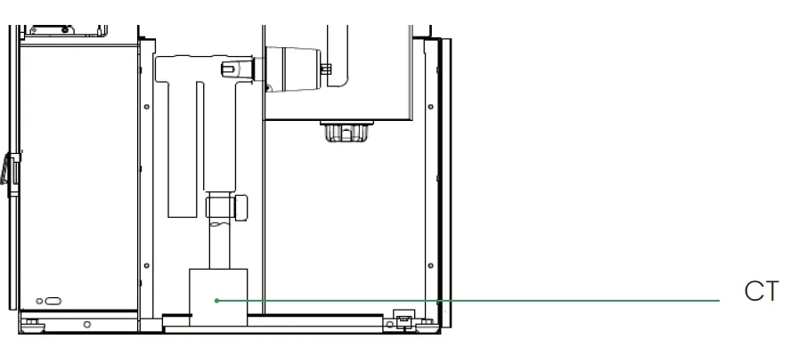
CT installation in the cable compartment
The ring-type CT can fit the incoming/outgoing cable and is fixed on the beam on the cable compartment, as shown as below.
CT installation on main busbar
The current transformer on main bus of BGS-40.5 can fi t the main bus and is fixed on the top of the cubicle

Voltage transformer
The voltage transformer (VT) in BGS-40.5 is designed with an insulated medium voltage terminal with a plug-in connector, and the VT is directly plugged into the special socket on the bottom side of the air tank. The VT core and the winding are integrated, and can be protected by a fuse (optional). The fuse is installed inside the VT and its current matches the short-circuit current withstand capacity. This effectively protects the VT when the power grid has problems, such as harmonics. Please see the figure below for VT with or without a fuse.
The VT secondary voltage is 100V, and the secondary core provides measurement and protection function. For example: 35/√3/0.1/√3/0.1√3/0.1/3kV. VT specific secondary core quantity, accuracy, capacity and other characteristics are determined when
ordering.

VT with fuse

VT without fuse
LV box
Brunstock’s LV box is modular and has a withdrawable design. The standard height is 500mm, which can be customised. The low-voltage components and accessories are designed according to customer requirements.

Outer cone cable connector
BGS-40.5 is equipped with cable bushings which comply with EN 50181 and IEC 60137 for termination of cables. The bushings fulfil the
requirements of DIN47636T1. The following cable bushings are used:
Interface C with M16 x 2 metric threads 400 series, In = 630 A
Standard on all modules and for side connection
Interface B with plug 400 series, In = 400 A
Optional for all modules.
The yellow area indicates the silver coated contact spring.
The installation instruction from the manufacturer of cable terminations must be followed. Be sure to lubricate the bushings thoroughly with silicone supplied
Important:
Where cables are not connected, the earthing switch must be locked in closed position or the bushings must be fitted with dead end receptacles before the unit is energised.
Cable terminations
All bushings are protected by cable compartment cover. The drawings below show typical arrangements with cable connectors.
The table below the drawings shows the distance A in millimetre from cable bushing to the inner part of cable compartment cover.

| | Distance A |
|---|---|
| Standard | 225mm |
| Double cables | 332mm |
| Three cables | 450mm |
| Three cables with surge arrestors | 569mm |
Surge arrester
 BGS-40.5 surge arresters use plug-in connection with the cubicle and can be categorised by two types cable bushings:
- Outer-cone bushing
Surge arresters should be located in the cable compartment. The specific technical parameters of arresters are determined when ordering.
The outer-cone comes with a rated voltage of 41, 42, 51, 52.7 or 54kV.
Interlock
Electrical interlock
- Electrical interlock can be achieved by intelligent control and protection unit’s contact detection and logic programming for position state of TPS and CB, and it can be achieved by microswitch as well
- The electrical interlock can be worked only when secondary power supply is powered
- Electromagetic lock is optional for ES
Mechanical interlock
- Mechanical interlock can only be achieved by operating the main shaft with TPS manually under certain conditions
- When circuit-breaker is closing, the manual operation cover of DS is interlocked. Only after the CB is opened, the cover can be freely opened, then the handle can be inserted into the hole for DS operation. whenever opened the cover manually, the CB cannot be operated electrically or mechanically
- Key lock and padlock is optional for CB/DS/ES upon request
Interlocking of the functional units
During the development of BGS-40.5, emphasis was placed on personnel safety and the reliability of the switchgear in operation. An interlocking system prevents any incorrect use. Thus, the operating levers can only be inserted if the service status permits it. Access to the cables compartment is only possible if the appropriate outgoing feeder is connected to earth.
These ring main units are equipped with the following interlocks:
Functional unit with vacuum circuit breaker, disconnector and earthing switch
Interlock status (IS)
| Interrupting mechanism | Position | IS DS open | IS closed | IS ES open | IS closed | IS CB open | IS closed | IS cable compartment panel |
|---|---|---|---|---|---|---|---|---|
| Disconnector (DS) | Open | - | - | Unlocked | Unlocked | Unlocked | Unlocked | - |
| DS | closed | - | - | Locked | - | Unlocked | Unlocked | - |
| Earthing switch (ES) | Open | Unlocked | Unlocked | - | - | Unlocked | Unlocked | Locked |
| ES | Closed | Locked | - | - | - | Locked | - | Unlocked |
| Circuit breaker | Open | Unlocked if ES open | Locked if ES closed | Unlocked | Unlocked if DS open | Locked if DS closed | Unlocked | - | - | - |
| CB | Closed | Locked | Locked | Locked | Locked | - | - | - |
Packaging
For road and rail transport: BGS-40.5 switchboard is packaged under protective sheeting. It is delivered fi xed on to a wooden pallet by two plastic tapes.
For maritime transport: BGS-40.5 is packaged in a heat-sealed cover with bags of desiccant, then enclosed in a wooden case with a solid leak tight bottom (including transport by container).
For air transport: BGS-40.5 switchboard is packaged in a wooden boxes (crates) with solid walls and a protective cover (dust cover).
Handling
The BGS-40.5 must be transported vertically:
When moving using a forklift: Only move the device on a pallet.
When moving without a pallet: A lifting sling must be hooked on to the switchgear’s lifting rings. The angle with the lifting sling must be at least 45°.
When transporting on pallet: Don’t tilt the switchgear. Respect the centre of gravity markings.
When transporting with slings: Use the two lifting rings.

Storage
BGS-40.5 must be packaged depending on the requirements for its planned storage duration. BGS-40.5 must be preserved intact in its factory origin packaging.
The storage area must not have any sharp and important changes in temperature. Consult us for any particular storage condition.
Brunstock product lifecycle
Brunstock representatives (subsidiaries and distributors) service their packaged products and solutions for the duration of their lifecycle according to their commercial agreements with customers. This would usually include planning and specifications prior to sales, implementation, operational support, optimisation and modernisation services, maintenance and dismantling at the end of each product’s life.

 Planning and specifications
Brunstock representatives help you to plan the full design and execution of your solution, to secure your process and optimise your time. With training provided by Brunstock, our reps usually offer the following:
- Technical feasibility studies: Accompany you to design a solution specifically for the given environment
- Preliminary design: Accelerate turn-around time to come to a final solution design
 Implementation
Brunstock representatives will help you to install efficient, reliable and safe solutions based on your plans.
- Project Management: Designed to help you complete your projects on time and within budget
- Commissioning: Ensures your actual performance versus design, through on-site testing, commissioning tools and procedures.
 Operate
Brunstock reps help you maximise your installation uptime and control your capital expenditure through their services. Please ask them for specific details about their:
- Advantage service plans: Customised services plans which cover preventive, predictive and corrective maintenance
- On-site maintenance services: Extensive knowledge and experience in electrical distribution maintenance
- Spare parts management: Brunstock reps are able to ensure spare parts availability and can help you optimise the maintenance budget for your spare parts
- Technical training: To build up necessary skills and competencies. In order to properly operate your installations in safety.
 Optimise and modernise
Brunstock reps propose recommendations for improved safety, availability, reliability and quality.
- Electrical assessment: Define improvement and risk management program
- Modernise switchgear fleet: With our SF6-free environmentally GIS

Frequency of maintenance intervention
BGS-40.5 switchgear is relatively maintenance-free. Depending on the exact configuration of the solution, we may recommend a schedule for maintenance activities to extend the life of your electrical distribution equipment and improve performance over time. Further information is available in the BGS-40.5 manual and can be discussed with your Brunstock representative.
 At the end of the BGS-40.5 service life
The dismantling and disassembly of BGS-40.5 is possible at the end of its service life. The separation of the elements making up the switchgear will be made:
- By disconnecting the mechanical connections
- By dismantling, breaking or shearing the connections
To guarantee efficient and ecological sorting and destruction of the materials, all plastic components have been identified. Your Brunstock representative will provide a description of the materials to you, their customer, along with information on the best valorisation process that recycling companies in your local area may need.
End of service life processing
Brunstock can support you in your BGS-40.5 end of service life processing approach.
Eliminate hazardous gas recovery
Due to the use of dry air, BGS-40.5 has no need for a process of any hazardous gas.
Composition of materials and valorisation at end of service life
After disassembly or dismantling, the recovered elements must be forwarded for treatment in the following manner:
| Type of waste | Destination | Recommended processing |
|---|---|---|
| Steel & stainless steel | Local recovery agent | Shredding, sorting and recycling |
| Alluminum alloy | Local recovery agent | Shredding, sorting and recycling |
| Non-ferrous metals | Local recovery agent | Shredding, sorting and recycling |
| Epoxy resin | Cement plant | Revalorisation at a lower added value |
| Thermoplastics | Local recovery agent | Incineration |
| Molecular sieve | Authorised network | Elimination |
| Soiled protective equipment | Authorised network | Incineration |
| Cables | Local recovery agent | Separation of sheathing and conductors |
![]()
When it comes to your electrical distribution installation, Brunstock representatives can help you:
- Increase productivity, reliability and safety
- Mitigate risk and limit downtime
- Keep equipment up to date and extend lifespan
- Cut cost and increase savings
- Improve your return on investment
This web page is a HTML version of the catalogue PDF (part 2 of 2). See part 1. You can download the PDFs about this product from the main SF6-free RMUs page.
You might also be interested in
Step-up stations
Green GIS
