Step up transformer substations for solar energy
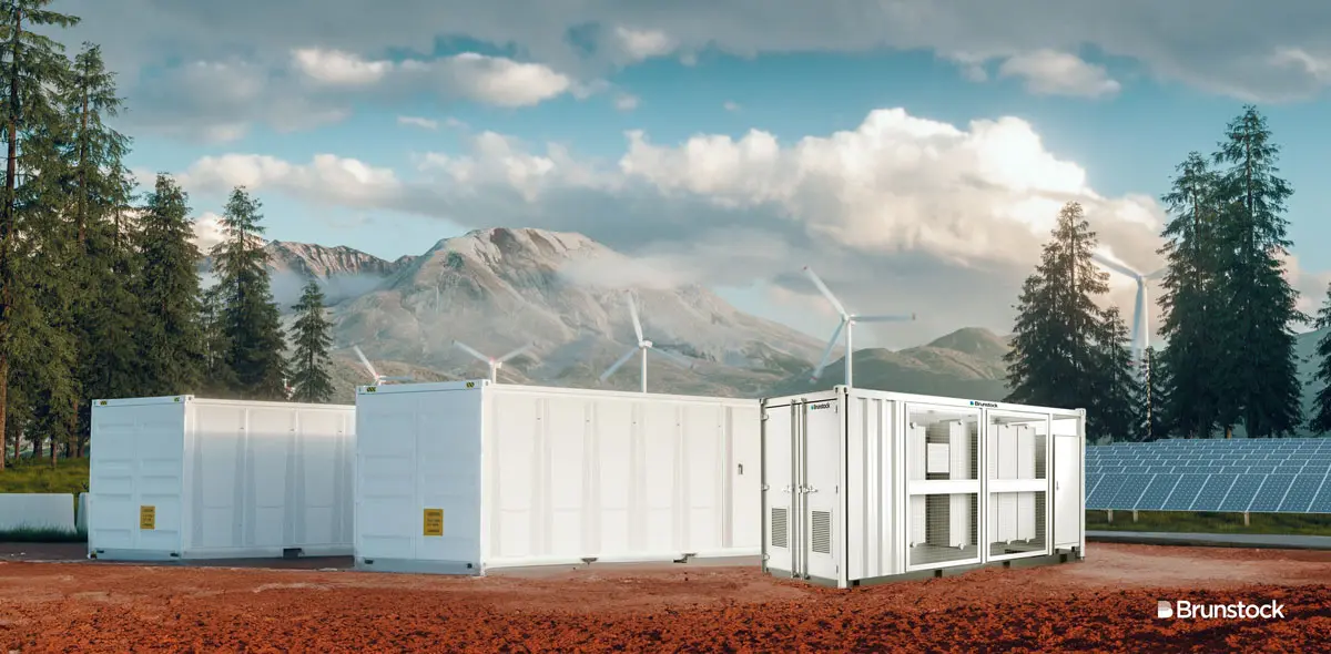
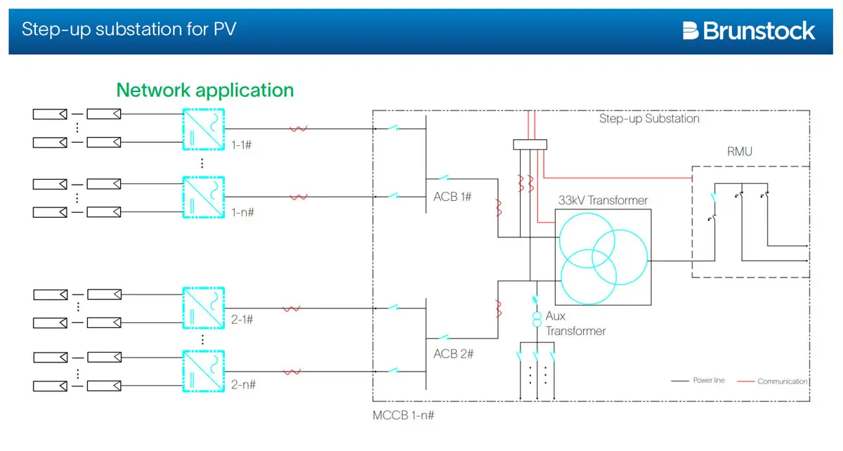
Brunstock’s step up transformer substations are designed to convert power on solar farms from LV to MV. Our modular pad mounted (metal-clad) substations convert low-voltage AC power generated by the PV inverter into medium-voltage AC power and feed it into the power grid.
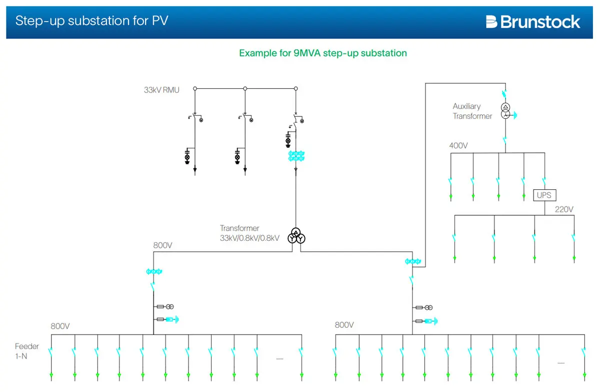
A Brunstock step up substation integrates a ring main unit (MV switchgear), a power transformer, a low-voltage cabinet and an auxiliary power supply into a steel container. This product provides a highly integrated power transformation and distribution solution for ground-based PV plants in medium-voltage grid-tied applications.
The modular design offers speed and commercial competitiveness while Brunstock also has the flexibility to cater for specific project needs. It is available in three MVA ratings:
- 3 MVA
- 6 MVA
- 9 MVA
Features of our step up transformer substation
Intelligent
- The substation detects the operating status of its ring main unit, transformer and LV switchboard in real time
- The substation displays power parameters online, with accurate current and voltage detection
- Remote access to the running information of the complete step up transformer substation
- Remote control of the circuit breaker for the low-voltage switchboard and ring main unit (RMU)
Manufacture
- Internal equipment is selected and installed
- The 20-foot container size of the skid structure facilitates easy transportation and installation
Reliable
- Solid and reliable structure design
- IP54 rating of medium-voltage/low-voltage rooms
Fast
- Fast deployment can be implemented
- Only low-voltage cables needs to be routed in and medium-voltage cables need to be routed out on site
Components of our step up transformer substation
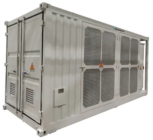

Appearance of our step up transformer substation

Exterior dimensions of PV step-up station
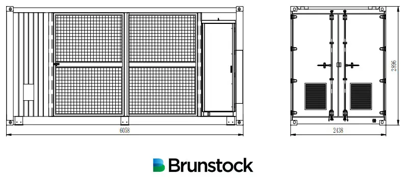
For ease of transportation, the substation has the same dimensions as a 20-foot container: 6,058mm wide x 2,896mm high x 2,438mm deep.
Internal composition
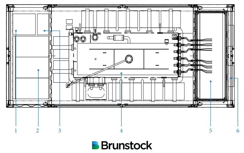
- Auxiliary transformer
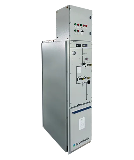
- Medium voltage (MV) switchgear ring main unit (RMU)
- Uninterruptible Power Supply (UPS) cabinet and communication box
- Transformer
- Low voltage (LV) cabinet
- Air conditioning
Technical data
Transformer technical data
| Type | 3,000kVA | 6,000kVA | 9,000kVA |
|---|---|---|---|
| Transformer Type | Oil transformer | Oil transformer | Oil transformer |
| Rated power | 3,000 kVA @ 40C (see note 1) | 6,000 kVA @ 40C (see note 1) | 9,000 kVA @ 40C (see note 1) |
| Max. power | 3,400 kVA @ 30C | 6,800 kVA @ 30C | 9,000 kVA @ 30C |
| Vector group | Dy11 | Dy11y11 | Dy11y11 |
| LV/MV voltage | 0.8kV/20-35kV | 0.8kV/0.8kV/20-35kV (see note 2) | 0.8kV/0.8kV/20-35kV (see note 2) |
| Maximum input current at nominal voltage | 2,500 A x 1 | 2,500 A x 2 | 4,000 A x 2 |
| Frequency | 50Hz | 50Hz | 50Hz |
| Tapping on HV | 0, ±2x2.5% | 0, ±2x2.5% | 0, ±2x2.5% |
| Efficiency | ≥99% | ≥99% | ≥99% |
| Cooling type | Oil natural air natural (ONAN) | Oil natural air natural (ONAN) | Oil natural air natural (ONAN) |
| Impedance | 6.5% (±10%) | 6.5% (±10%) | 9.5% (±10%) |
| Oil type | Mineral oil (PCB free) | Mineral oil (PCB free) | Mineral oil (PCB free) |
| Winding material | AI/AI | AI/AI | AI/AI |
| Insulation class | A | A | A |
MV switchgear technical data
| Type | 3,000kVA | 6,000kVA | 9,000kVA |
|---|---|---|---|
| Insulation Type | Depends on GIS chosen (see note 6) | Depends on GIS chosen (see note 6) | Depends on GIS chosen (see note 6) |
| Rate current | 630 A | 630 A | 630 A |
| Internal arcing fault | IAC AFLR 20kA/1s; 25kA/1s | IAC AFLR 20kA/1s; 25kA/1s | IAC AFLR 20kA/1s; 25kA/1s |
| Qty of feeder | 2-3 feeders | 2-3 feeders | 2-3 feeders |
| MV surge arrester for VCB | Optional (see note 3) | Optional (see note 3) | Optional (see note 3) |
LV panel technical data
| Type | 3,000kVA | 6,000kVA | 9,000kVA |
|---|---|---|---|
| ACB specification | 2,500 A / 800 Vac / 3P, pcs | 2,500 A / 800 Vac / 3P, 2 pcs | 4,000 A / 800 Vac / 3P, 2 pcs |
| MCCB specification | 250 A / 800 Vac/ 3P, 1 * 17 pcs | 250 A / 800 Vac/ 3P, 2 * 17 pcs | 320 A / 800 Vac / 3P, 2 * 15 pcs |
Protection technical data
| Type | 3,000kVA | 6,000kVA | 9,000kVA |
|---|---|---|---|
| AC input protection | Circuit breaker | Circuit breaker | Circuit breaker |
| Transformer protection | Oil temperature, oil level, oil pressure | Oil temperature, oil level, oil pressure | Oil temperature, oil level, oil pressure |
| Relay protection | 50/51, 50N/51N | 50/51, 50N/51N | 50/51, 50N/51N |
| LV over voltage protection | AC Type II (optional: AC Type I + II) | AC Type II (optional: AC Type I + II) | AC Type II (optional: AC Type I + II) |
| Anti-rodent protection | C5-Medium | C5-Medium | C5-Medium |
Solar step up transformer station general technical data
| Type | 3,000kVA | 6,000kVA | 9,000kVA |
|---|---|---|---|
| Dimensions (W x H x D) | 6,058mm x 2,896mm x 2,438mm | 6,058mm x 2,896mm x 2,438mm | 6,058mm x 2,896mm x 2,438mm |
| Weight (approx.) | ≤5T | ≤22T | ≤28T |
| Operating temperature range | -25C ~ 60C (see note 4) | -25C ~ 60C (see note 4) | -25C ~ 60C (see note 4) |
| Auxiliary power supply | 5 kVA/400V (optional: max. 40kVA) | 5 kVA/400V (optional: max. 40kVA) | 5 kVA/400V (optional: max. 40kVA) |
| 2kVA UPS | Optional (see note 3) | Optional (see note 3) | Optional (see note 3) |
| Degree of protection | IP54 | IP54 | IP54 |
| Allowable relative humidty range (non-condensing) | 0-95% | 0-95% | 0-95% |
| Operating altitude | 1,000m (standard) / greater than 1,000m (optional) see note 5 | 1,000m (standard) / greater than 1,000m (optional) see note 5 | 1,000m (standard) / greater than 1,000m (optional) see note 5 |
| Communication | RS485, ethernet, optical fibre | RS485, ethernet, optical fibre | RS485, ethernet, optical fibre |
| Compliance | IEC 60076, IEC 62271-200, IEC 62271-202, IEC 61439-1, EN 50588-1 | IEC 60076, IEC 62271-200, IEC 62271-202, IEC 61439-1, EN 50588-1 | IEC 60076, IEC 62271-200, IEC 62271-202, IEC 61439-1, EN 50588-1 |
- For more details on the AC power, please refer to the de-rating curve
- Rated output voltage from 20 kV to 36 kV, more available upon request
- Extra features are availabe that the standard product doesn’t contain, more options upon request
- When ambient temperature ≥55oC, an extended roof will need to be installed onto the substation on site by the customer
- For higher operating altitude, please consult with your Brunstock rep
- For more information on our secondary switchgear, please review BGS-12, BGS-24, BGS-40.5 and BGP-40.5
Product design of our step up transformer substation
LV switchroom design
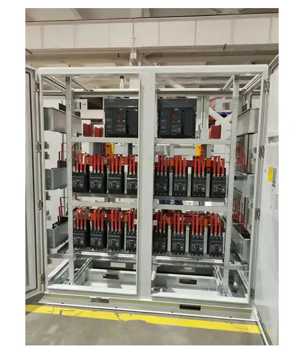
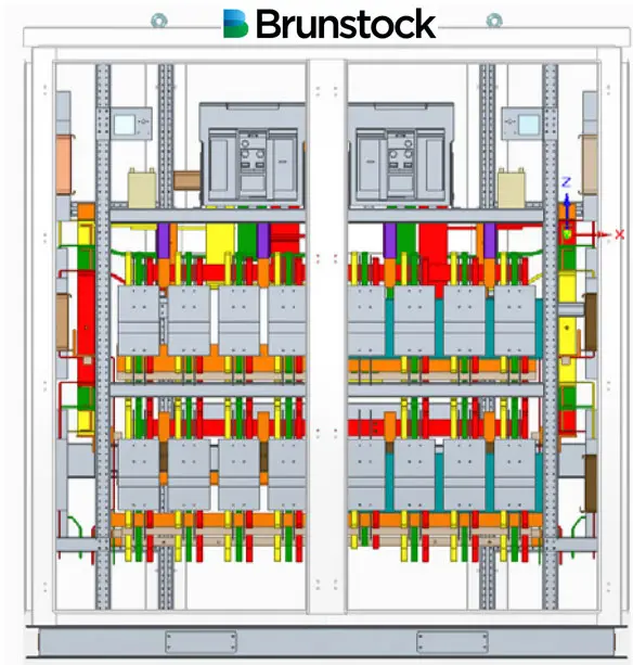
The LV cabinet is located inside a dedicated LV room inside the step-up substation. It is used to converge and transmit low voltage from the inverter to the step-up transformer and feed it into the MV grid. The LV cabinet consists of a LV Air Circuit Breaker (ACB), a Moulded Case Circuit Breaker (MCCB) and other electric components. Taking the 9,000kVA as an example, the figure shows the internal components of the LV cabinet.
Low-voltage switchgear technical data
| Type | Measure | Description |
|---|---|---|
| Standard compliance | IEC 61439 | |
| Rated voltage | V | AC800 |
| Insulation voltage | V | AC1,000 |
| Ingress protection | IP | IP65 |
| Rated short circuit withstand current Icw | kA | 50/1 |
| Impulse withstand voltage Uimp | kV | 12 for incoming / 8 for feeders |
| Main switch-ACB | | Fixed, manual/electric operation, Ui=1,250V, Uimp=12kV, Ue-800V, In=4,000A, Icu=75kA at 800Vac, Icw=75kA-1s, TMD |
| Branch-MCCB | | Fixed, manual operation, Ui=1,000V, Uimp=8kV, Ue=800V, In=320A, Icu=50kA at 800Vac, TMD |
| Branch-MCCB | | Fixed, manual operation, Ui=1,000V, Uimp=8kV, Ue=800V, In=250A, Icu=50kA at 800Vac, TMD |
| Input AC cable terminal | | Screw connector, Cu or Al, max 300mm2 |
| Cable entry | | Based on specific design |
| SPD | | Uc=1,500V |
| Power meter | | Current, voltage, active and reactive power, etc |
| Air conditioner | Unit | 2 |
| Dimension | mm | L2,240 x D1,040 x H2,400 |
| Ingress protection | IP | IP55 |
Power transformer room
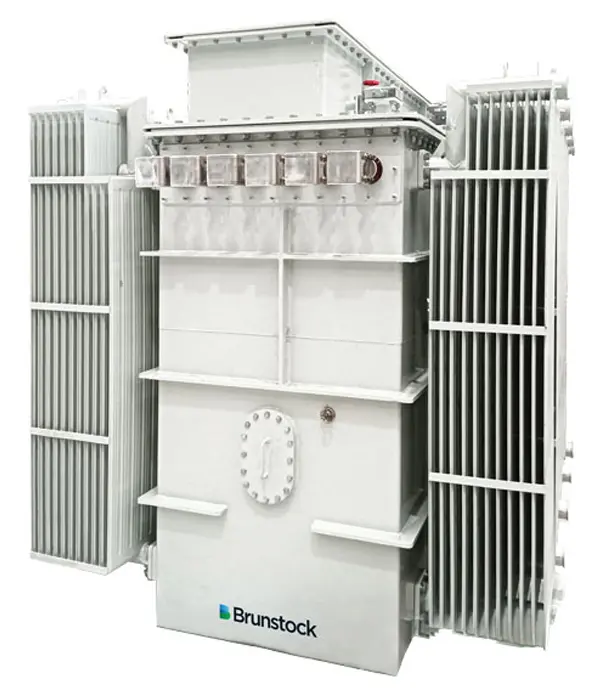
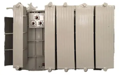
The transformer room mainly includes a transformer inside, which is used to convert the low-voltage AC power into medium-voltage AC power. The transformer integrates accessories such as a pressure relief valve, tap changer, oil level indicator, pressure gauge, oil temperature indicator, oil filling valve and oil drain valve.
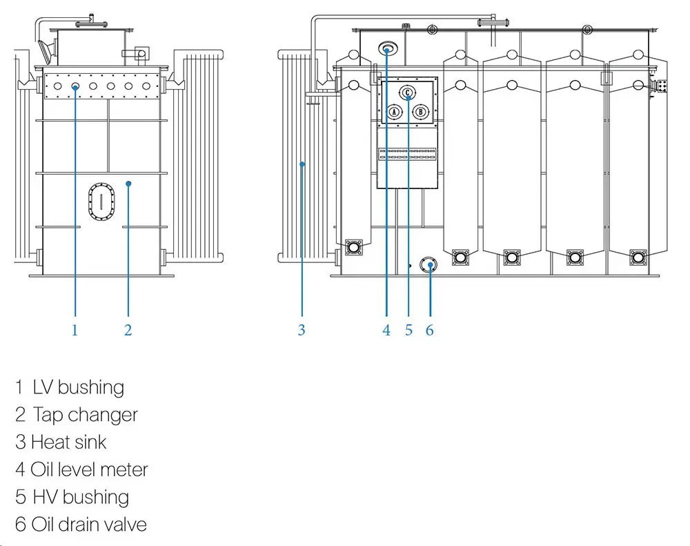
The structure of 9,000kVA is shown in the figure above. The oil-cooled transformer adopts natural heat dissipation, and the top is not covered.
Step up transformer technical data
| Items | Measure | 9,000/33, 3 windings, oil immersed |
|---|---|---|
| Rated output | kVA | 9,000 |
| Vector group | | Dy11y11 |
| Type of cooling | | ONAN |
| Rated voltage HV | kV | 33 |
| Rated voltage LV | kV | 0.8 |
| Rated voltage | Voltage variation | ±10% |
| Rated current HV | A | 154 |
| Rated current LV1 | A | 3,248 |
| Rated current LV2 | A | 3,248 |
| Number of phases | | 3 |
| Rated frequency | Hz | 50 |
| Frequency variation | % | ±5 |
| Conductor materials HV | | Aluminum |
| Conductor materials LV | | Aluminum |
| Tap changer LV | | Off circuit |
| Tap Changer HV | | ±2x2.5% |
| Insulation level HV | kV | LI 170/AC 70 |
| Insulaton level LV | kV | AC 5 |
Note: for more transformer ratings please see our Transformers product information or consult with your Brunstock rep.
| Dimension | mm | W3,600 x D2,200 x H2,600 | |
| Weight | Core and winding | kg | 8,700 |
| Weight | Oil | kg | 4,000 |
| Weight | Others | kg | 4,935 |
| Weight | Total | kg | 17,635 |
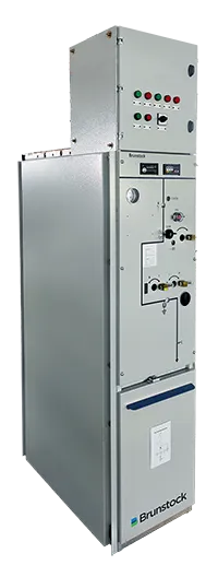
Medium voltage switchroom
The medium-voltage room contains a Brunstock gas-insulated secondary ring main unit. Read more about our green GIS products, which contain dry air: BGS-12 and BGS-40.5. We also offer BGS-24, which contains SF6 gas.
The circuit breaker offers transformer protection mainly through the relay protection device. When the transformer is overloaded or short-circuited, the circuit breaker will disconnect. When the transformer experiences an over-temperature fault, heavy gas fault, or oil over pressure fault, the circuit breaker trips and the system is quickly protected.
The medium-voltage room also contains a communication box and a power distribution cabinet.
Auxiliary power supply
Our auxiliary power supply system consists of an auxiliary transformer, auxiliary power supply box and UPS. Both the external and internal components of the cabinet can be supplied by Brunstock.
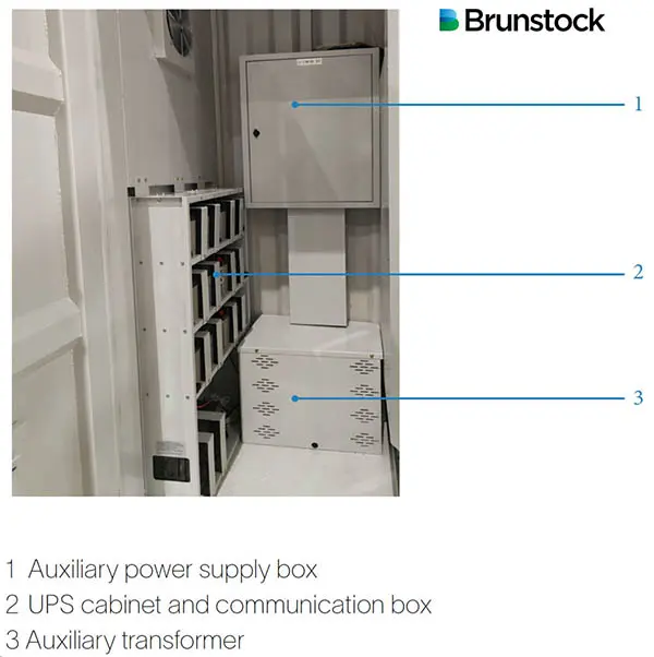
Auxiliary power supply technical data
| Auxiliary transformer | Measure | Description |
|---|---|---|
| Transformer type | KVA | 15 (5~15, optional greater than 15) |
| Rated voltage | V | 800/400 |
| Connection symbol | | Dyn11 |
| Auxiliary transformer enclosure dimension | mm | W400 x D400 x H500 |
| Auxiliary transformer location | | MV compartment, floor mounted |
| Power supply box | ||
| Incoming MCB | Pcs | 1, 63/C32A,3P, OF |
| Feeder MCB | Pcs | 5, 63/C16/10/6A,2P, 400V |
| Feeder MCB | Pcs | 4, 63/C32/6A,2P, 220V |
| Dimension | mm | W600 x D180 x H800 |
| UPS | ||
| UPS | Set | 1 x 2kVA/ 2h, or on request |
| Battery | Pcs | 6 x 12V/7Ah, or on request |
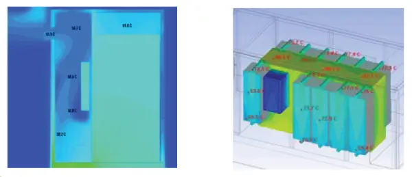
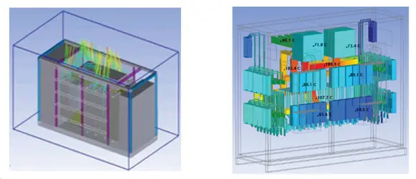
Thermal design
Considering the different working conditions and requirements for each compartment
and component, Brunstock’s step-up substation adopts different cooling methods
for different compartments:
- The ingress protection level of the LV room/cabinet is high, so air conditioning is used to take away the LV room/cabinet indoor heat
- The MV transformer adopts ONAN mode
- The MV switchgear and the communication and power distribution cabinet adopt
the cooling method of natural cooling via vents, air intake from the bottom and air
extraction by the fan above.
Our science-based cooling structure design ensures cooling efficiency and effectively extends the service life of internal components and the entire container.
Below: Flow field analysis of step-up substation
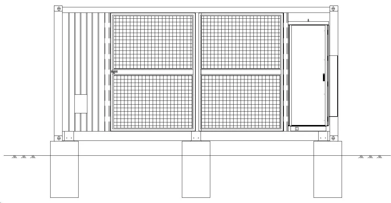
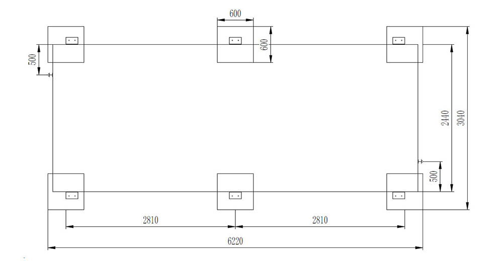
Step up transformer substation foundation
Brunstock Step-up Substation Downloads

You might also be interested in
Step-up stations
Green GIS
